
Adding a New Rule Set
How to confirgure a new rule set and subsequent rules
Considering that technical requirements may consist of multiple rules, ATLAS model rules are set up under rule sets, whereby an overall rule set may contain one or more specific rules that fulfil an overall requirement.
Custom model rules can only be configured by ATLAS admin users.
Accessing the Model Check Admin Area
-
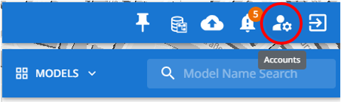
Click upon the 'Account Settings' menu option within the right hand menu panel.
-
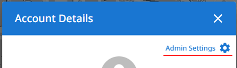
Within the Account Setting spop-up, click on the 'Admin Settings' link.
-
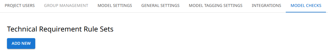
Within the Settings page, select the 'Model Checks' tab.

Adding a New Rule Set
-
On the ATLAS Settings page, select the 'Model Checks' tab and click upon 'Add New'.
-
Within the 'Create Rule Set' window, specify:
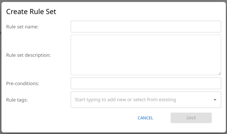
- Rule set name (mandatory)
- Rule set description
- Pre-conditions: these may be specific considerations that the end user should be aware of.
- Rule tags (mandatory): adding rule tags enables rules to be grouped by tag, and allows them to be run against a model via the selection of the tag(s) rather than specific rule name.
-
Click 'Save' to create the rule set.
The rule set will then appear within the rule set table.
Adding Rules to Rule Sets
-
Within the Rule Set table, click 'View/Edit' against a rule set.

-
Within the Rule Set window, click on 'Add Rule'
-
The Create custom rule window will open with the following input fields:
- Check Type:
- Automated: Automated checks are those that will execute against a model when the Model Rules are run. Rule types have to be configured against automated rules for them to work against a model.
- Manual: Manual checks can be detailed within ATLAS for when a rule can't be automated, but still needs to be checked as part of model verification. When Model Rules are run against a model, manual checks will appear as failures within the results table to indicate that they need to be undertaken against the model before they are marked as approved.
- Rule Number
- Rule Notes
- File: a document can be uploaded to provide further information or context to a rule. For example a diagram that explains what the checks are covering.
- Rule type:
- Single Asset Class (A): Single asset class checks are checks that apply directly to the model elements that fall under the asset class(es) defined in the check configuration.
- Asset Class (A) to Asset Class (B): Asset Class (A) to Asset Class (B) checks provide the means of checking proximities between model elements.
- Check Type:
-
Upon populating the initial rule details, click on 'Save'
-
On saving the chosen Rule Type section will expand to show which check types can be configured (see Custom Model Rules).
Single Asset Class (A) checks
Setting the Asset A Class

-
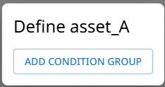
Click on the 'Asset A' button. This will open the 'Define asset_A' dialog window. This is where the specific conditions to be used to define which model elements will be identified as Class A, are defined.
-
Click on 'ADD CONDITION GROUP'.
-
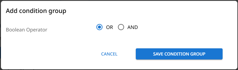
Selecting the Boolean Operator; this selection determines how the subsequent conditions will be treated within the class definition logic. Once selected, click 'Save Condition Group'.
-
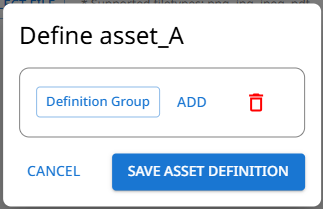
A Definition Group has now been created. Click on the 'Definition Group' button to add the group conditions.
-
Within the Update Condition Group window, specify how a Class A element will be defined from its model properties.
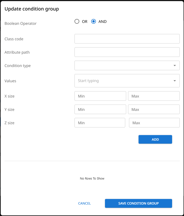
- Boolean Operator - this is the field previously set, but can be updated if necessary.
- Class Code or Attribute Path
-
Class Code: Entering a known Class code will mean that model elements that are identified with the class code will be treated as a Class A asset.
-
Attribute Path: If the class of an element can be defined by values against one or more of its model properties (attributes), the specific attribute path(s) can be entered, followed by a condition and a value.
The attribute path field is free text entry and is case sensitive, therefore the attribute name shall be entered exactly how it appears within the model data.
If an attribute sits under an attribute group (property set (PSET)), then the group name should be added as a prefix followed by 2 underscore characters;[group_name]__[attribute_name]
- Condition type: Select the matching condition for the subsequent attribute value.
- Value: Enter the value to be matched within the attribute specified.
-
- X, Y, Z Sizes: If you need to further constrain the classification of an element by its size, enter the necessary dimension values (m), against the relevant axis.
- When the defining conditions have been set as required, click 'Add'. The condition will then be added to the condition table.
If you are defining a class by multiple conditions, you can add further conditions and they will appear in the table.
The Boolean operator selected, will come into play against the multiple conditions.
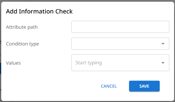
Information Checks
Used to verify model data to ensure it adheres to requirements.
-
Attribute Path: The attribute path field is free text entry and is case sensitive, therefore the attribute name shall be entered exactly how it appears within the model data.
If an attribute sits under an attribute group (property set (PSET)), then the group name should be added as a prefix followed by 2 underscore characters;[group_name]__[attribute_name]
-
Condition type: Select the matching condition for the subsequent attribute value.
-
Value: Enter the value to be matched within the attribute specified.
Geometry Checks
Used to verify model element geometry against a template model.
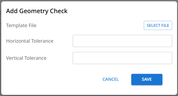
- Template File: Opens the file upload dialog window to allow the selection of a model file for upload.
- Horizontal/Vertical Tolerances: Enter tolerance values in metres (m). These values will be taken into account during the geometry comparison process to determine whether model element geometry aligns with the template file geometry. Differences beyond the tolerance values will be classed as failures.
Area Checks
Used to verify whether an element covers a specified area within the given plane.
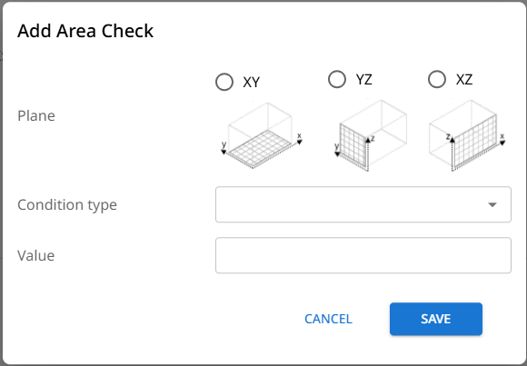
- Plane: The selection of which 2D plane in which to measure the specified area value.
- Condition type: Select the matching condition for the subsequent area value.
- Value: Enter the area value to verify.
Gradient Checks
Used to verify that a surface of a model element has an acceptable gradient.
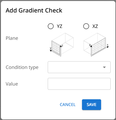
- Plane: Selection of the plane in which the maximum slope of an element's top surface will be measured.
- Condition type: Select the matching condition for the subsequent gradient value.
- Value: Enter the gradient value to verify. The value should be in decimal format, e.g. 0.5 for a 1:2 ratio gradient.
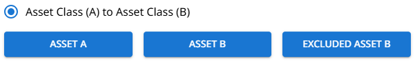
Asset Class (A) to Asset Class (B) checks
If you require elements within a model to adhere to specific proximities, asset class (A) to asset class (B) checks allow you to build the checks to verify the these proximities.
- If you need to check that a type of element within a model is at a certain proximity from all other elements within a model, you only need to set up an asset class definition for 'Asset A'.
- To check the proximity between two or more element types, provide asset class definitions for 'Asset A' and 'Asset B'. Note that the elements defined under 'Asset A' will be those against which the pass/fail check results will be recorded.
- For either of the above check scenarios, if certain elements need to be excluded from the checks, their asset class definitions can be set under the 'Excluded Asset B' option.
Setting the Asset Classes
-
Click on the relevant 'Asset' button. This will open the 'Define asset' dialog window. This is where the specific conditions to be used to define which model elements will be identified as Class A, are defined.
-
Click on 'ADD CONDITION GROUP'.
-
Selecting the Boolean Operator; this selection determines how the subsequent conditions will be treated within the class definition logic. Once selected, click 'Save Condition Group'.
-
A Definition Group has now been created. Click on the 'Definition Group' button to add the group conditions.
-
Within the Update Condition Group window, specify how the classification of an element will be defined from its model properties.
- Boolean Operator - this is the field previously set, but can be updated if necessary.
- Class Code or Attribute Path
-
Class Code: Entering a known Class code will mean that model elements that are identified with the class code will be treated as a Class A asset.
-
Attribute Path: If the class of an element can be defined by values against one or more of its model properties (attributes), the specific attribute path(s) can be entered, followed by a condition and a value.
The attribute path field is free text entry and is case sensitive, therefore the attribute name shall be entered exactly how it appears within the model data.
If an attribute sits under an attribute group (property set (PSET)), then the group name should be added as a prefix followed by 2 underscore characters;[group_name]__[attribute_name]
- Condition type: Select the matching condition for the subsequent attribute value.
- Value: Enter the value to be matched within the attribute specified.
-
- X, Y, Z Sizes: If you need to further constrain the classification of an element by its size, enter the necessary dimension values (m), against the relevant axis.
- When the defining conditions have been set as required, click 'Add'. The condition will then be added to the condition table.
If you are defining a class by multiple conditions, you can add further conditions and they will appear in the table.
The Boolean operator selected, will come into play against the multiple conditions.
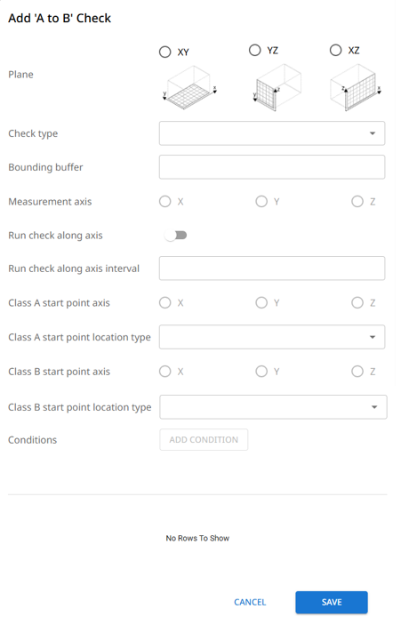
A to B Checks
Use the A to B checks to verify proximities between elements within a model.
-
Plane: Select the plane in which to measure the proximity to other elements.
-
Check Type:
- Planar: This option will check the proximity within the selected plane, in any outward direction from elements defined under 'Asset A'.
- Line: This option will check the proximity within the selected plane, only in the outward direction of the specified measurement axis for elements defined under 'Asset A'.
-
Bounding Buffer: Specify a bounding buffer in metres (m). The bounding buffer sets the maximum dimensional bounds that you want the check to be undertaken from the outer edge of the elements that are defined under 'Asset A'. Any elements that fall outside of this bounding buffer will not be considered during the check.
-
Measurement Axis: To restrict the direction of the proximity measurement to a single axis available in the selected plane, chose the desired axis.
-
Run check along axis: if a proximity measurement needs to be taken at regular intervals along an asset A element, in the axis perpendicular to the selected plane, use this option. Along with this selection set an interval value within 'Run check along axis interval'.
-
Run check along axis interval: Specify in metres (m), the interval distance to take proximity measurements when the 'Run check along axis' is set to true.
-
Class [A/B] start point axis: Select the planar axis from where to take the proximity measurements from.
-
Class [A/B] start point location type: Select the position along the selected axis from which to take the measurement from.
- Min: The minimum position along the axis (datum point).
- Max: The maximum position along the axis away from the datum point.
- Mid: The mid point along the axis.
- Closest to other: The point along the axis that is detected as the closest to the element being checked against.
-
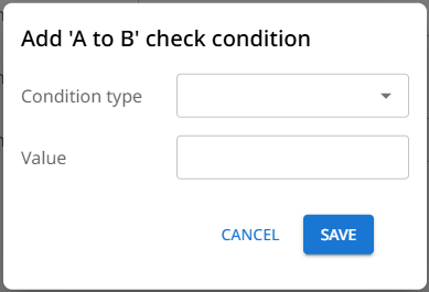
Conditions: Specify the proximity conditions and distance values. To check if a proximity is within a range, set up one condition for the minimum distance and another for the maximum distance.
Updated 5 months ago