
Level of Geometry (LoG) Verification
Verifying a that model contains valid geometry
Level of Geometry (LOG) verification allows verification of elements (assets) within an overall design model, against template geometry for the specific element (asset) class.
This ensures that design models are using valid geometry if your overall models utilise a catalogue of individual model elements. For example you may have a catalogue of bench seating models that have been agreed for use, and want to ensure that the bench seating elements within a design model match one of the available benches from the catalogue, and haven't had their geometry edited beyond the permitted tolerances.
Pre-requisites
Asset Configuration
To be able to use the LOG verification, at least one asset configuration must be defined for your project.
See Asset Configurations on how to create and manage your Asset Configurations within ATLAS.
Asset Templates
Within the Asset Configuration, the asset classes you wish to involve in the LOG checks, must have at least one asset template assigned.
LOG Check Process
For each element within the overall design model the following steps are undertaken:
- Check that the model element contains the "object_name" attribute.
- Check that the object_name for the element matches the name of a Template held against the selected asset configuration.
- Compares the model element geometry with the Template geometry.
Running a LOG Check
-
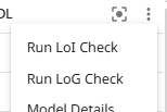
Navigate to the model menu for the model to be checked.
-
Select 'Run LOG Check'
-
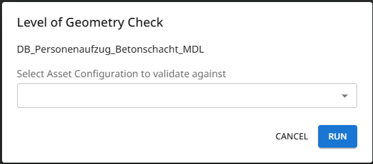
Within the dialog box, select the Asset Configuration and Level of Information to check against
-
Click Run
-
Whilst the checks are running:
- a processing icon will appear against the notification bell icon,
- a notifcation will be provided when the check starts, which includes a estimated run duration,
- The option for 'LOG Check' will become inactive within the model menu.
-
On completion of the check:
- a completion notification will be given,
- a notification email will be sent,
- the check results are viewable through the 'LOG Check' option under the model menu.
If a check fails, a failure notification is provided.
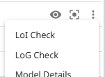
If a LOG check has previously been run against the model, then the 'Run LOG Check' model menu option will instead display as 'LOG Check'. This option will open the results of the previous check.
There is the option to 'Re-run Check' from within the results table.

Viewing Check Results
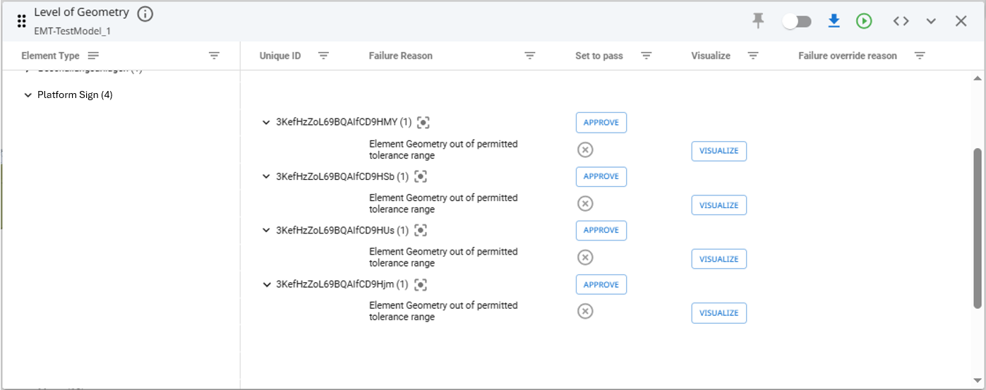
After a LOG check has been run against the model, the model menu option will display as 'LOG Check'. This option will open the results of the check.
The results table will display within the model view. The table only includes the model elements that have failed and indicates the failure reason along with other supporting information.
Visualising Geometry Failures
For LOG failures where the model element geometry does not align with the matched template geometry, an option to visualise the discrepancies is provided. Selecting the 'Visualise' option will open an additional window within the view that shows an isolated view of the chosen element.
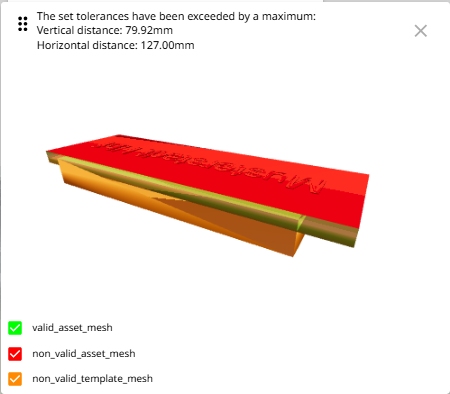
This window, indicates the maximum dimensional discrepancies, both vertical and horizontal.
- Green 'valid_asset_mesh' geometry indicates where the model element and template align.
- Red 'non_valid_asset_mesh' geometry indicates where model element geometry is additional to what is held in the template.
- Orange 'non_valid_template_mesh' geometry indicates where the model element is missing geometry that exists within the template.
Failure Reasons
- [object name] does not match any templates for [asset configuration] - means that there are no templates named with the object name of the model element, and therefore no LOG check can be completed.
- Missing object name - means the model element has no 'object name' attribute, and therefore no template matching can take place.
- Element Geometry out of permitted tolerance range - means that the model element geometry is not within the matched template's defined dimension tolerances.
- Template id [x] invalid model - means there is an error with the model file uploaded for the matching template.
Overriding Failures
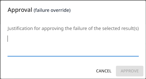
If after reviewing the check results you determine that a failure is actually acceptable and should not be classed as a failure. Against each failed element row is an 'Approve' option within the 'Set to pass' column.
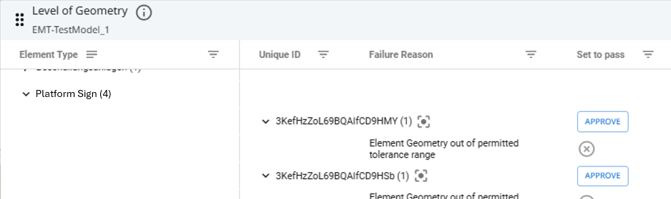
Click 'Approve' to enter an approval justification against the element.
Overriding Multiple Failures
If you wish to override multiple failures in one action, filter the results table to display the desired failures. Within the table header, click on 'Approve Filtered' and assign your failure override reason.

This will approve and apply the failure override reason to all rows under the active filter.
Editing/Removing Failure Overrides
To edit/remove an override of a failure at model element level, locate the desired overridden failure, then click upon the pencil icon against the override reason.
- Edit the message to update it.
- Delete the message to remove the override.
To edit/remove an override of a failure added as a multiple override, apply the table filters to return the desired overridden failures, then click upon the pencil icon against the override reason.
- Edit the message to update it.
- Delete the message to remove the override.
Overridden failures will not be included within BCF exports.
Exporting Check Results
Check results can be exported within a BCF file to allow sharing of information with others. This allows for corrections to be addressed prior to subsequent model revisions being uploaded to ATLAS.
To export the BCF file, click on the download icon from within the results table.

Updated 5 months ago